 To acquire a three-dimensional model with David Scan is enough to be in possession of free software made available by the product’s website. The basic kit provided by the company at a price of € 499 (in basic webcam + laser version) and includes a number of standard components. The real problem of this type of scanner is the low quality of the mesh in the free version of the software, for this reason many trials were necessary before the final scan. For the project I replaced the components supplied with homemade items at the price of about € 20. Specifically, the components in the same order as they appear on the website, are:
- A camera (e.g. web cam):
a Microsoft webcam, fitted with a screw on the bottom that would allow to tie it on a tripod (by the laser kit) at total price of € 9.90. There are no special care in choosing this item. It ‘just that it is possible to change the settings for contrast and brightness for a better control of acquisition; - A hand-held line laser:
a small garden – with built-in level – laser that projects a red laser-ray linear enough to be perceived by the webcam. The cost of this item was € 10.90, but with a more powerful laser, probably, we would get better results; - Two plain boards in the background:
plans background were constructed with a cardboard box cropped on which were glued sheets with markers for calibration. Important to remember not to use clear tape, because the laser on the surface reflects its radius and causes a lot of artifacts. Is necessary that there is’t reflective surface on the box space; - A Windows PC:
using for editing a Mac, I decided to use for the acquisition of an old laptop PC on which I’ve installed Windows XP as the operating system. The results, in terms of performance, are excellent; - Free software DAVID-laserscanner:
downloaded by David’s website;
Step 1 – Scanner preparation
As a first step it was necessary to build the scanner. It was enough to put together all the elements mentioned above and then calibrate the camera with printed markers of the box. At this stage it is necessary to increase the brightness of the webcam and align markers with respect to larger, I used a dvd box to slightly raise the tripod and put it in line with them. There was no need to change the ambient light, as for this stage to be perceived that the real picture of the default background. Then the tests were carried scan to adjust the webcam and the light environment. A bright light may affect the reflections of the laser and cause many errors during acquisition. Initially the base of the box was white, then I inserted a small black backing to prevent reflections. To support the object I used rolls of toilet paper clipped. In the following pictures you can see some shots of this phase of work. There have been many tests to verify the proper movement to be performed with the laser, the right distance from the object and the scrolling speed of the ray.
Step 2 – Acquisition
After the calibration phase, the time has come in which the object should be acquired by the David Scanner. Now it is necessary that there is little light, that there are no reflective surfaces in contact with the laser-beam and that the webcam is not moving. Webcam settings must be changed to improve the acquisition and ensure that there are artifacts. The contrast must be very high, while the brightness should be lowered as much as possible, in this way they are perceived only the useful rays and not those reflections. The scans, for each face, were made taking the model in front of the webcam and scrolling the laser from the top down several times. Scan each face lasted from 30 to 50 seconds, some sides were acquired more than once to get an acceptable result. Acquiring final 11 scans were performed by rotating the object on the vertical axis and on its base. The major problems in this phase were caused by the straw of the whistle and the details are too small to be acquired by the David Scanner in these conditions. In addition, the David Scanner software in the free version does not allow you to save the mesh in high quality, this has a great influence on the final result, it created difficulties in processing.
…and a small video example of a typical acquisition phase of the object:
Step 3 – Mesh elaboration
Once the acquisition of the mesh was necessary to put them together and reconstruct the surface in order to have a compact and navigable. This processing was done with MeshLab, and below are listed the various stages of processing and is divided into several sub-steps, for clarity.
3.1 Cleaning meshes
As a first step it was necessary to clean each individual mesh. In fact, David Scanner, being a very cheap solution, produces many artifacts that are likely to be amplified in the later stages of processing. It ‘important to be very careful not to delete faces or vertices of importance for the reconstruction of the surface, so it is a work of great care and patience. MeshLab offers the following filters and tools that have been used in this phase of processing. Selection: vertex, face in a rectangular region, connected components in a region; Delete: selected faces, selected faces and vertices, selected vertices.
3.2 Surface recostruction
After cleaning the mesh, are passed to the operations of surface reconstruction. The first thing to do is to align every mesh with the others. To do this, there is the tool: “Align tool” of MeshLab, with it you can glue one or more meshes with another mesh. With “Point Based Glueing” you can offer a first rough alignment indicating at least 4 matching pair of points on the meshes. After this you can process and an algorithm tries to align the surfaces in a better way. It should repeat this process until all the meshes acquired will not have sufficiently covered the surface of the object. In this case, the operations were very quick in drawing given the low quality of the meshes. The final model consists of the union of 10 meshes; there are 97,705 vertices and 167,785 faces.
Once all the meshes have been aligned, it is necessary to reconstruct the surface. First it was necessary to bring together all the meshes into a single entity, the command was “Flatten Layers visible” and created a single resulting mesh, the number of faces and vertices is the same as the sum of the total project.
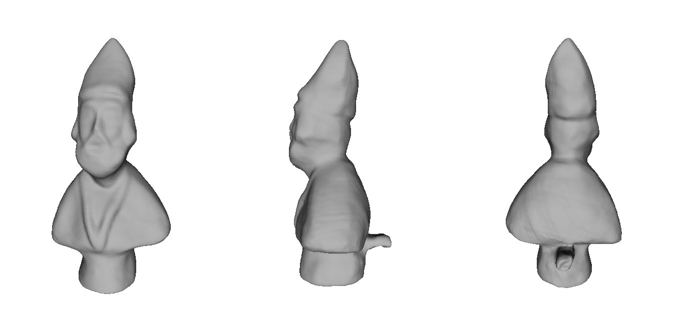
We can then go to the reconstruction of the surface, I decided to use Poisson. The algorithm of this filter uses points and normal to reconstruct the surface, and was chosen because it is able to reconstruct the model even in areas where there are no faces or vertices. Despite being an automatic process, the resulting surface is very faithful to the original while losing a lot of detail. After some testing of settings, the final result was achieved by setting the Octree Depth to 14. The processing is 5207265 msec duration, about 1 hour and 26 minutes. After that we got a model with a closed area of 83,771 vertices and 167,538 faces.
Step 4 – Enjoy it!
Now the model is ready to be used: go to the viewer >>
Or download ply object: ![]() download model (*.ply)
download model (*.ply)